

Desertcart purchases this item on your behalf and handles shipping, customs, and support to Sri Lanka.
๐ Elevate your DIY projects with a display thatโs as sharp as your vision!
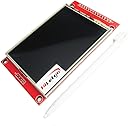
The HiLetgo ILI9341 2.8" SPI TFT LCD Touch Panel offers a vibrant 240x320 resolution with a white LED backlight and RGB vertical stripe pixel arrangement. Designed for seamless integration, it supports both 3.3V and 5V logic levels (with level shifting) and includes a PCB with power supply IC and SD card compatibility, making it a top choice for professional-grade embedded and DIY electronics projects.
| ASIN | B073R7BH1B |
| Best Sellers Rank | #40,063 in Industrial & Scientific ( See Top 100 in Industrial & Scientific ) #13 in LCD Touch Panels |
| Color | Red |
| Customer Reviews | 4.4 4.4 out of 5 stars (326) |
| Date First Available | July 6, 2017 |
| Item Package Quantity | 1 |
| Item Weight | 1.94 ounces |
| Item model number | 3-01-1433 |
| Manufacturer | HiLetgo |
| Material | FR4 |
| Package Dimensions | 4.02 x 3.94 x 0.87 inches |
| Part Number | 3-01-1433 |
| Size | 2.8" SPI TFT LCD Display |
| Voltage | 5 volts |
K**K
Works with Teensy 3.2 or Arduino - here's how
I love these displays and use them on all my projects. I've bought about 8 so far and can get them to work with either Teensy 3.2 or an Arduino Nano. For operation with a Teensy 3.2 1. use the <ILI9341_t3.h> from the PJRC--and this lib is very fast connect directly 2. for touch use "UTouch.h" 3. for SD I use <SdFat.h> 4. no level shifters needed 5. you may need to solder J1 (I do on all my displays) 4. if you want to use SD, remove the resistors R1, R2, R3 and solder 0 ohm resistors For operation with Auduino Nano 1. use the <Adafruit_ILI9341.h> 2. for touch use "UTouch.h" 3. for SD I have yet to get an SD to work with graphics due to not enough memory 4. no level shifters needed 5. you WILL need to solder J1 (I do on all my displays) EDIT as of 12/29/2019 Usage with Arduino connect as usual but power your Arduino with 3.3 volts (just connect 3.3 to the 5V pin on the arduino). Alternatively you can put a 1K series resistor on all pins to drop the voltage going to the unit (and power with 3v3). THESE UNITS WILL NOT WORK IF POWERED WITH 5 AND IF THE SIGNAL LINES ARE 5 VOLTS. update 2/2/2022 tips on usage to get everything working on a teensy 4.0 (or 3.2) /* This simple program will test 1) the display, 2) the SD card, 3) the touch screen, 4) ability to readPixel The readPixel is only supported by some display drivers like the ILI9341_t3 driver, there is a PrintScreen.h utility that will let you save your screen to a BMP file and draw the file if readPixel fails try to adjust speeds above. It's possible the display MISO is not tri state and will basically own MISO where other devices can't use it. If so, you will need some external buffer magic If using display with Teensy (3v3) solder J1, replace R1, R2, R3 with 0 ohm pin connections Display MCU VCC 3v3 GND GND CS 10 RESET 3v3 If white screen 1) 8 or 2) use series 1K0 and 10uf to GND to slow charge DC 9 MOSI 11 SCK 13 LED 3v3 or connect to analog pin and use analogWrite(x) to fade brightness MISO 12 T_CLK 13 T_CS 0 T_DIN 11 T_DO 12 T_IRQ 1 SD_SCK 13 SD_MISO 12 SD_MOSI 11 SD_CS A3 (other digital pins may work, read data sheet for what pins support CS) */ #include "ILI9341_t3.h" // high speed display that ships with Teensy #include <XPT2046_Touchscreen.h> // touch driver for a TFT display #include <SdFat.h> #include <SPI.h> #define CS_PIN 10 #define DC_PIN 9 #define T_CS 0 #define T_IRQ 1 #define SD_CS A3 int BtnX, BtnY; // you know the drill ILI9341_t3 Display(CS_PIN, DC_PIN); XPT2046_Touchscreen Touch(T_CS, T_IRQ); TS_Point TouchPoint; SdFat sd; SdFile dataFile; void setup() { Serial.begin(9600); while (!Serial) {} Serial.println("Starting..."); // start the dispaly Display.begin(); Display.setRotation(1); // depending on your exact display getting touch + SD + display working // you may need to adjust the clock speed // default is 30 mhz but you may need to slow to 10000000 or set to as high as 100000000 //Display.setClock(20000000); // start the touch Touch.begin(); Touch.setRotation(1); // start the SD card // depending on your sd card and display, you may need to slow the sd card clock // I find 20 mhz to be pretty reliable bool SDStatus = sd.begin(SD_CS, SD_SCK_MHZ(20)); //bool SDStatus = sd.begin(SD_CS); // test SD and write something if (SDStatus) { Serial.println("SD OK"); dataFile.open("Test.txt", FILE_WRITE); dataFile.print("This is a test"); dataFile.close(); } else { Serial.println("SD failed"); } // test display Display.fillScreen(ILI9341_BLUE); Serial.print("Color of pixel (10,10): "); Serial.println(Display.readPixel(10, 10)); delay(4000); Display.fillScreen(ILI9341_BLACK); } void loop() { if (Touch.touched()) { TouchPoint = Touch.getPoint(); BtnX = TouchPoint.x; BtnY = TouchPoint.y; // consistency between displays is a mess... // this is some debug code to help show // where you pressed and the resulting map // x = map(x, real left, real right, 0, width); // y = map(y, real bottom, real top, 0, height); // tft with black headers, yellow headers will be different BtnX = map(BtnX, 3700, 300, 0, 320); BtnY = map(BtnY, 3800, 280, 0, 240); // Serial.print(", Mapped: "); // Serial.print(BtnX); // Serial.print(","); // Serial.println(BtnY); Display.fillCircle(BtnX, BtnY, 3, ILI9341_RED); // delay(5); } }
B**M
Great, and it is slow, BUT you can do partial refreshes
Works great. As others have mentioned it's slow doing a full screen refresh. However, it does support doing partial updates, which are significantly faster. For example, using the Adafruit Python Driver, you can call the image function and give it just part of the screen you want to update. This is nearly instantaneous, and has worked well for me.
C**R
Works fine once you get past a few gotchas
Let me state, it works, it works as expected and I like the display. Let me get you over a couple of gotchas. First off, no joke on the 3.3V logic. You can't use an UNO for testing, it just doesn't work. I can think of a chipset I haven't been able to cheat it but 5V = doesn't function (worked fine after I switched processors, I didn't cook mine). I got mine working on an Arduino MKR. I tied reset to the MKRs VCC, I plugged the display VCC into the 5V pin. I used the Adafruit ILI9341 library and the display test ran after I look the "LED" pin and tied it to pin 6 and did the told digitalWrite(6, HIGH); on the top line of setup();. I then tested the touch screen with the XPT2046 library, there is only one out there from memory. One note... the MISO/MOSI lines are NOT connected as some online walkthroughs state... so you'll need to switch wires over for bench testing. I used the example with IRQ and put my CS on pin 5 and IRQ on pin 4. The sensitivity of the display matched my expectations for a resistive touch screen (vs capacitive). For the hassle I prefer the Adafruit version but with a little extra effort it's worth the lower cost.
A**N
Great little display for the money
Bought this display to use as a control screen for an Amateur (Ham) Radio project. It has a few warts, mainly because it uses a resistive touch screen and the X-Y coordinates aren't always consistent for a given point on the screen. Aside from that, it runs well on the Teensy 3.6 we used as an MPU for the project, doesn't draw a lot of current and once we got a calibration routine working reliably, the touch screen works great. The standard ILI931 libraries work just fine and we used the SPIN-Master touch library for the touch which also works fine with the Teensy 3.6. Still a work in progress, but the project is nearly complete and with a few minor tweaks to the various X-Y coordinate ranges for touch controls on the screen it will be ready to play. I only gave it 4 stars because of the sometimes erratic X-Y coordinates returned by the touch panel but otherwise it IS a good value for the money and most people won't need the extra precision point coordinates I'm trying to achieve (mostly successfully, I might add). W0EB
T**.
Use buffer gates as level shifters for longer connection distances
These inexpensive TFT touchscreens work well once you learn what works and what doesn't. I recommend using level shifters (if using an Arduino) to decrease all OUTGOING DATA SIGNALS from 5V to 3.3V. The MISO / T_DO INCOMING DATA from TFT to Arduino does not need to be shifted up to 5V since Arduinos recognize voltages over 2.5-3.0V as HIGH. In order to allow further distance (longer connections) from Arduino to TFT, I had to scrap the bidirectional TXS0108E level shifters that are commonly used and switch to SN74AHCT125 buffer gates. These shift voltage unidirectionally (5V to 3.3V -- which is all that is needed) and are much quicker and output more amperage to overcome capacitance in the wires, allowing much longer distances between Arduino and TFT--great for SPI communication. Also, Vcc and LED voltage to TFT can be 5V, but all data signals should be 3.3V. Once I scrapped the bidirectional level shifters and went to the buffer gates, my connection distance increased from only 6-8 inches to over 30 inches.
G**R
don't forget to initialize theconstructor with the reset pin
It works well. Initially, I ran into problems with this - all I was getting was a white screen with an Arduino Uno and an Adafruit Feather, and the Adafruit ILI9341 libraries weren't working. I contacted HiLetgo and they were very friendly and helpful and sent me an email with all the schematics I needed. After perusing them for a bit, I realized that this unit is actually a 3.3V unit.. If you're connecting it to an Uno or a Feather, you'll need to buy a bidirectional logic level shifter to convert the SPI pins, DC and RST pins from 5V to 3.3V. Also, when you're using the Adafruit library, don't forget to initialize the constructor with the reset pin, otherwise, you'll have errors at times. Something like: Adafruit_ILI9341 tft = Adafruit_ILI9341(TFT_CS, TFT_DC, TFT_RST); Also, use hardware SPI pins with this unit preferably.
P**L
Nice bright display - easy to get working
Very easy to get working - I added this to an an ESP8266 controller, from HiLetgo to build an alarm clock that is time synchronized to an NTP server. The instructions provided by HiLetgo on Amazon for the ESP8266 https://smile.amazon.com/gp/product/B010N1SPRK got me going very quickly, the only part I had to change was step 3 where it said use: esp8266com_index.json. This URL periodically seems to go off line, and was unavailable when I was setting up, so instead I downloaded the source, and used that locally. I also added an oled display from HiLetgo and ran an example sketch to display wifi networks. The idea is to use the TFT display to show the time, while the oled display will show the alarm time(s). It as very easy to wire up the hardware and get the examples running - now just need to spend some time writing the software. As all three items are running from the 3.3 volt supply, I bridged the J1 connector with a blob of solder, which bypasses the onboard regulator. I started running from an external supply, but the whole thing only seems to be drawing 150mA and the onboard regulator is spec'd at 800mA so now for development I am running it all from the USB power, the regulator is barely warm!
I**N
ILI9341
Hi quality and great for price. Connection is a little bit complicated but working great for projects (game console, LVGL and etc)
D**E
Works well
Works well
A**A
ottimo display, ma non funziona la scheda SD per leggere le immagini
B**D
If a logic level shifter is used these displays work with 5V Arduinos
The easiest and least complicated way to use these displays is to connect them to a device that has 3.3V logic, an ESP32 board for example. I chose to connect this display to an Uno R4 WiFi before reading the fine print and it didn't work. In fact I thought I fried the display. After reading the fine print I tried including logic level shifters in the circuit and discovered my "fried" display was still good. I used https://www.amazon.ca/dp/B074M8TM81?ref=ppx_yo2ov_dt_b_fed_asin_title available here on Amazon. The downside to using logic level shifters are: 1) the additional expense and 2) slower display updates. Again the best way to use these displays is with a 3.3V microcontroller.
Trustpilot
3 weeks ago
1 week ago