


π§ Elevate Your Debugging Game!
The Treedix 2pcs JTAG Breakout Board Adapter is a high-performance tool designed for seamless programming and debugging of ARM-based circuit boards. Featuring a 10-pin 2.54mm connector and a 200mm flexible ribbon cable, this adapter is compatible with a variety of JTAG/SWD debuggers, making it an essential addition to any developer's toolkit.
| ASIN | B09JKBMPKZ |
| Batteries Required? | No |
| Batteries included? | No |
| Best Sellers Rank | 294,219 in Computers & Accessories ( See Top 100 in Computers & Accessories ) 660 in Serial Adapters |
| Colour | Grey |
| Customer Reviews | 4.2 4.2 out of 5 stars (10) |
| Date First Available | 15 Oct. 2021 |
| Item Package Quantity | 1 |
| Item Weight | 32 g |
| Item model number | Treedix |
| Manufacturer | Treedix |
| Package Dimensions | 12.4 x 8.61 x 1.8 cm; 32 g |
| Shape | Flat |
| Size | with 2.54mm pitch 10pins IDC cable |
| Special Features | Data Transfer |
C**Y
Well made and extremely useful to adapt wiring between full size and this small size JTAG connector cable. With this breadboard and another similar one for the full size connector you're free to map the signal however you need them. Premade adapter boards containing both size connectors only provide one fixed mapping which didn't suit my needs.
S**E
I bought this little adapter board to use with a very common display module that Arduino enthusiasts play around with. (The JY-LKM1638 F71A 8 Digital Tube + 8 Key + 8 Double Color LED Module ). The board has two JTAG connectors for inputs and outputs and comes with a ribbon cable with the JTAG plug on both ends. I wanted a breakout module where I could plug in the other end of the ribbon cable and wire the connections to my Arduino circuit. This module provides that capability. The solution is not perfect. This module was obviously made for some specific application because the printed pin labels donβt match the functions of my display board connector. Also, when I plug in the included ribbon cable, the red wire is not on my pin1, but rather on pin 10. Neither is a deal breaker, because once I wire up my circuit I wont be reading the silk screened labels on the board and the key on the cable connector only lets you plug it in one way. No problems like those mentioned by others. Looking at the front of the module: Pin Use Use Pin 1 MOSI VCC 2 3 NC GND 4 5 RESET GND 6 7 SCK GND 8 9 MIS0 GND 10 Looking at the front of the JY-LKM1638 board: Pin Use Use Pin 1 Vcc Gnd 2 3 Clk Data 4 5 Strobe0 Strobe1 6 7 Strobe2 Strobe3 8 9 Strobe4 Strobe5 10
D**Z
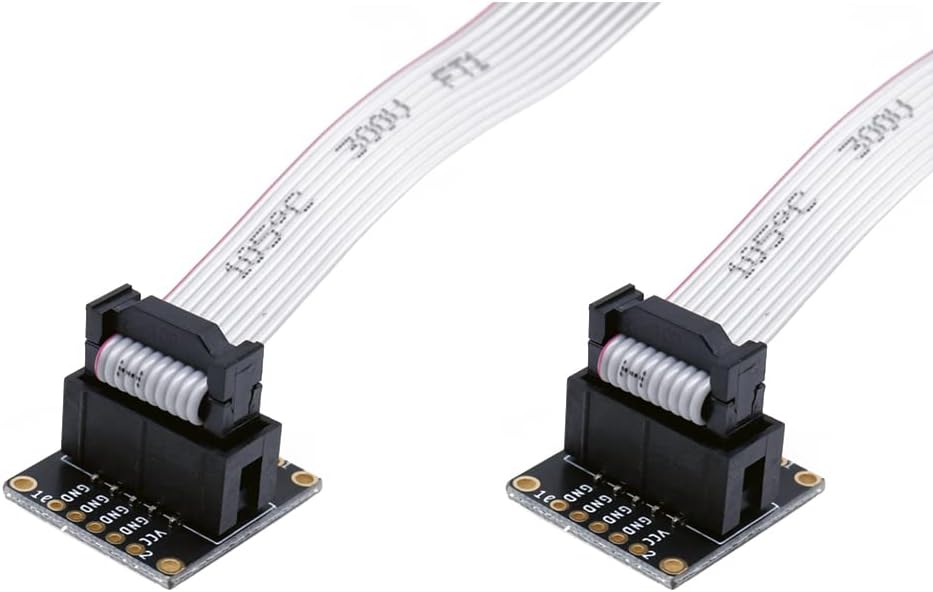
I purchased this break out board to use with a JTAG board for ESP32 source code level debugging. While electrically it would probably work, it had a couple of mechanical issues for my application and probably yours. I intended to solder on some standard breadboarding pins that I've use with other boards (e.g. from adafruit) and plug it into my standard breadboard. I specifically bought the 0.1" spacing board for this intent. The pin-to-pin spacing isn't an issue, but the spacing between the two banks of holes is not a multiple of 0.1" and won't fit in the breadboard ... couldn't even bend the pins a little. Also, more minor issue is that the labelling was for SPI, not JTAG. Finally, and even yet more minor, the way the ribbon cable is crimped, it covers up most of the labels anyway. So, I could make it work, but in the end, I just resorted to breadboard jumper cables to make my connections.
D**L
Pinouts are labeled backwards compared to Adafruit. Grounds should be on keyed 1/2 of 10 pin connector. Returning for refund.
Trustpilot
1 month ago
2 weeks ago