
Desert Online General Trading LLC
Dubai, United Arab Emirates
Desert Online General Trading LLC
Dubai, United Arab Emirates


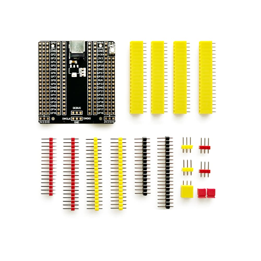


🚀 Elevate your Raspberry Pi Pico game with the ultimate breakout board!
This Treedix-compatible breakout board is designed specifically for the Raspberry Pi Pico, offering 26 GPIO pins, multiple communication ports, and a flexible 6.5-12V input range. Compact and easy to solder, it streamlines prototyping and sensor integration, making it an essential expansion for any maker or developer aiming to push their projects further.
| RAM | LPDDR4 |
| Brand | Treedix |
| Series | Treedix |
| Item Weight | 1.13 ounces |
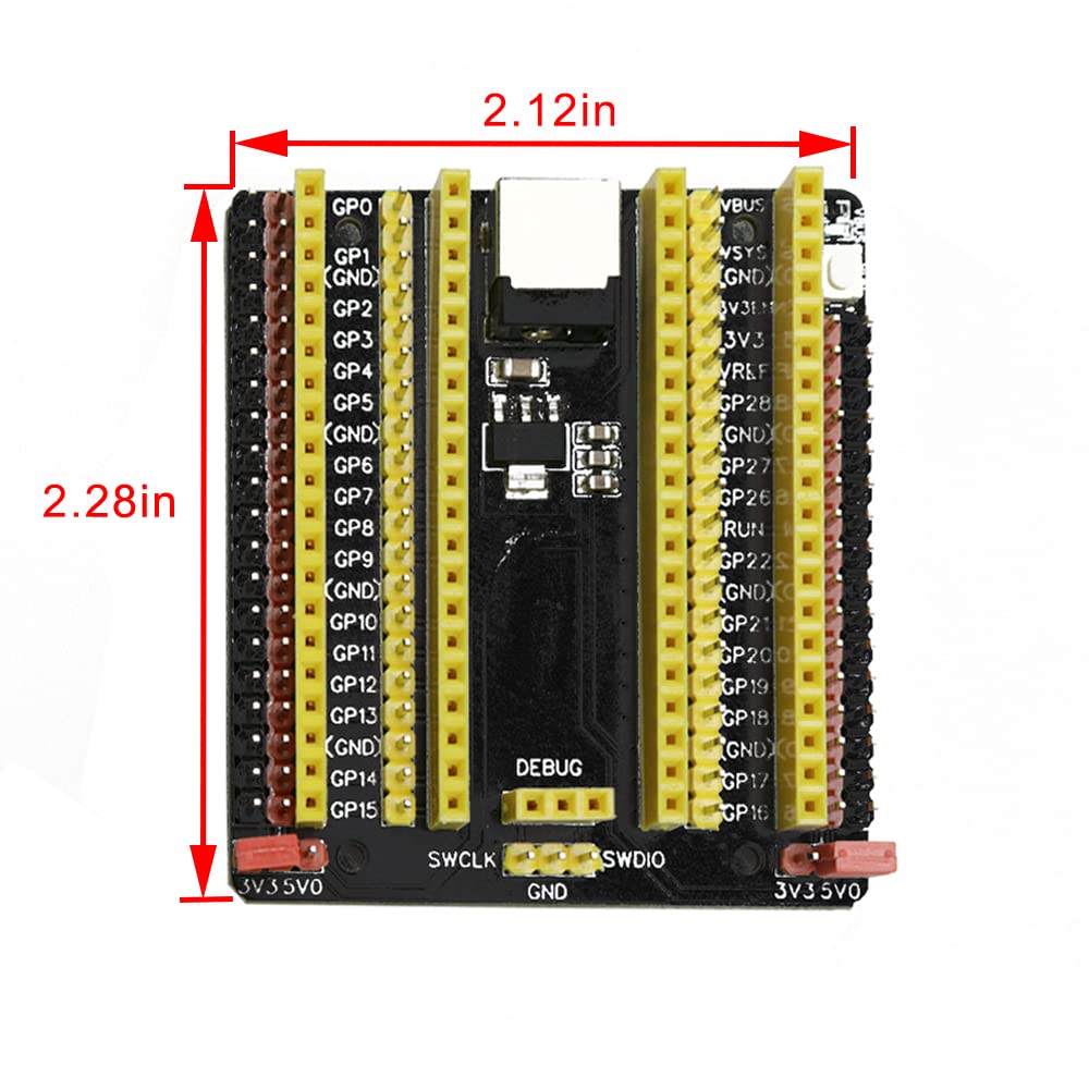
| Product Dimensions | 2.28 x 2.12 x 0.06 inches |
| Item Dimensions LxWxH | 2.28 x 2.12 x 0.06 inches |
| Number of Processors | 1 |
| Manufacturer | Treedix |
| ASIN | B0BNPJKWTM |
| Date First Available | December 1, 2022 |
Y**S
USEFUL ADAPTER
VERY USEFUL ADAPTER
J**E
A lot of work
This is a decent product but if ya know what your doing. I couldn’t find a lot of documentation on this after purchase. Companies like this have a constant flow of code snippet and projects available but seem to offer little in the way of extra value. What I mean is it would be beneficial for these companies to give teach new coders and programmers the extent of what these devices can accomplish. It is easy to get discouraged in this field and on top of having to painstakingly assembly this, after your done your left quite clueless if not familiar with micropython, c+, microcontrollers, or these packages with titles require experience in of the self’s to assemble. It would be a good business move and opportunity to educate. Instead you get a piece of paper the size of a business card. Do better
G**2
Every RP2040 or Pi Pico Needs One of These
This is not a beginner soldering project. It sure is nice to see pin labels and have to ability to use both female and male jumper wires. GND and VCC buss's are very handy.Clean Backside of board with alcohol or mild soap.I set my soldering iron to 400-425 female headers seem to need more heat.Here's the order that I assembled mine. See Photos1. Put 3 pin connectors in breadboard, position board onto connectors and solder2. Solder VCC and GND Connectors, I used the jumpers supplied to hold them together and keep them straight. Do Both sides.3. Leave jumpers on VCC and GND connectors, place female header into place, use tape to secure it to GND and VCC connectors, then solder. Repeat for other side4. Attach 2 Female headers to Microcontroller and install in holes on board, use finger to hold and solder.5. This one is tricky, hold male header with finger and Solder one pin inspect for straightness, solder rest.Backside - add some solder to barrel connector mine needed some extra, inspect for solder pieces and shorts. Remove jumpers from VCC and GND Connectors and place in appropriate 3.3v or 5v positions.Took a good 45 minutes - EnjoyUpdate 2/14/23 - You might want to switch the male and female headers so you can hook up servos. You can use an external power supply for the servo's. Not sure why they showed it the way I soldered it. Reversing the headers gives you more flexibility without any drawbacks.
S**N
it's great
got to solder the pins on. everything worked good.
J**J
great expansion board but the bottom heats up and starts to smoke.
This is a good expansion mod, i love having the extra power pins. I switchted the female and mail yellow strips so i could connect 3 pin connector right to the board. I havent been able to use this because when ever i connect a board to it the bottom heats up so much it feels like its going to start on fire. so i have to disconnect the usb from the board. im not not using the power port.
Trustpilot
5 days ago
1 week ago